Future Production Technologies
- Continuous mixing (Twin-screw extruder)
- Trajectory mixing
- Extrusion-based coating
- Dry Coating: Electrostatic spraying
- Dry Coating: Brush application
- Dry Coating: Electrostatic fluidized bed deposition
- Dry Coating: Free-standing electrode fabrication
- Dry Coating: Direct calendering
Multilayer Coating - Drying: Vertical-Cavity Surface-Emitting Laser (VCSEL)
- Drying: Diode laser
- Drying: Near-Infrared (NIR)
- Roll-to-Roll Vacuum Drying
Across Processes:
- Pre-Lithiation
- Mini-Environments
- Rotative High-Speed Single Sheet Stacking
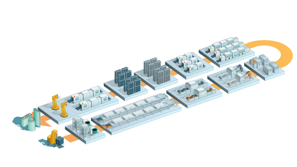
Introduction
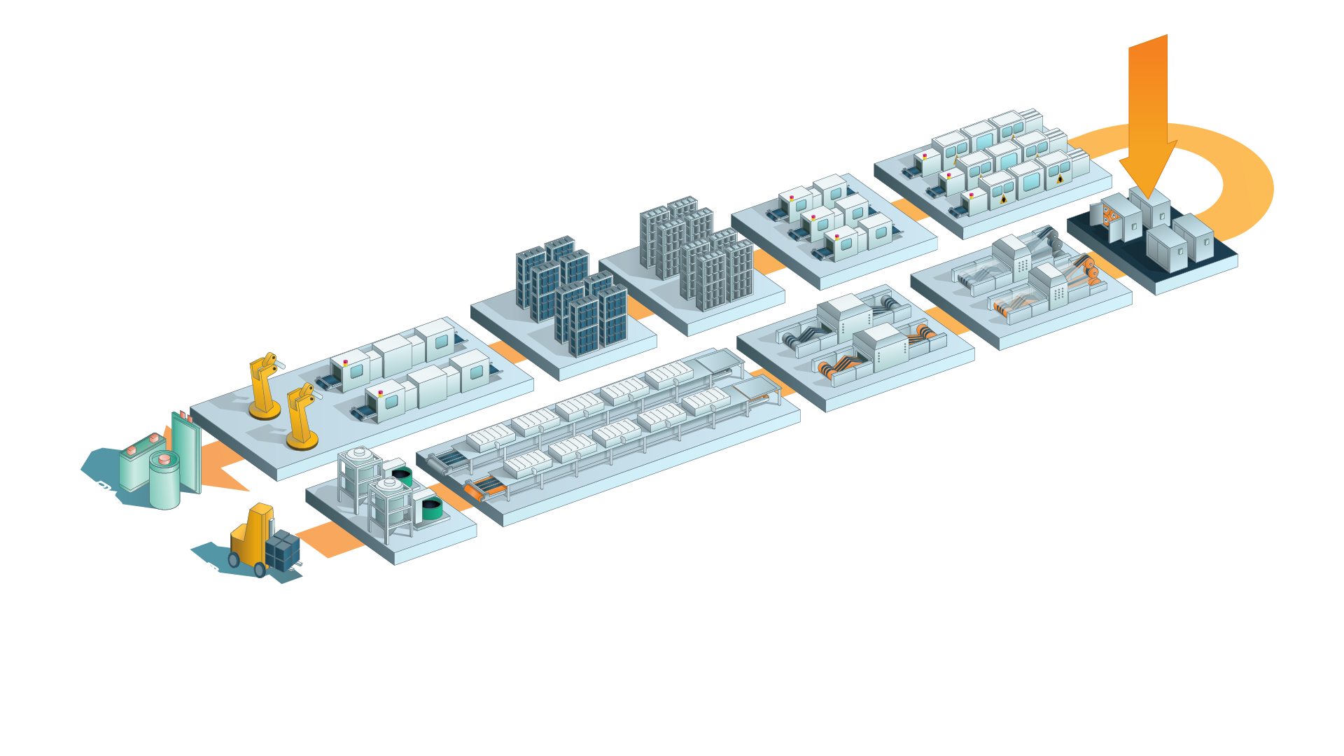
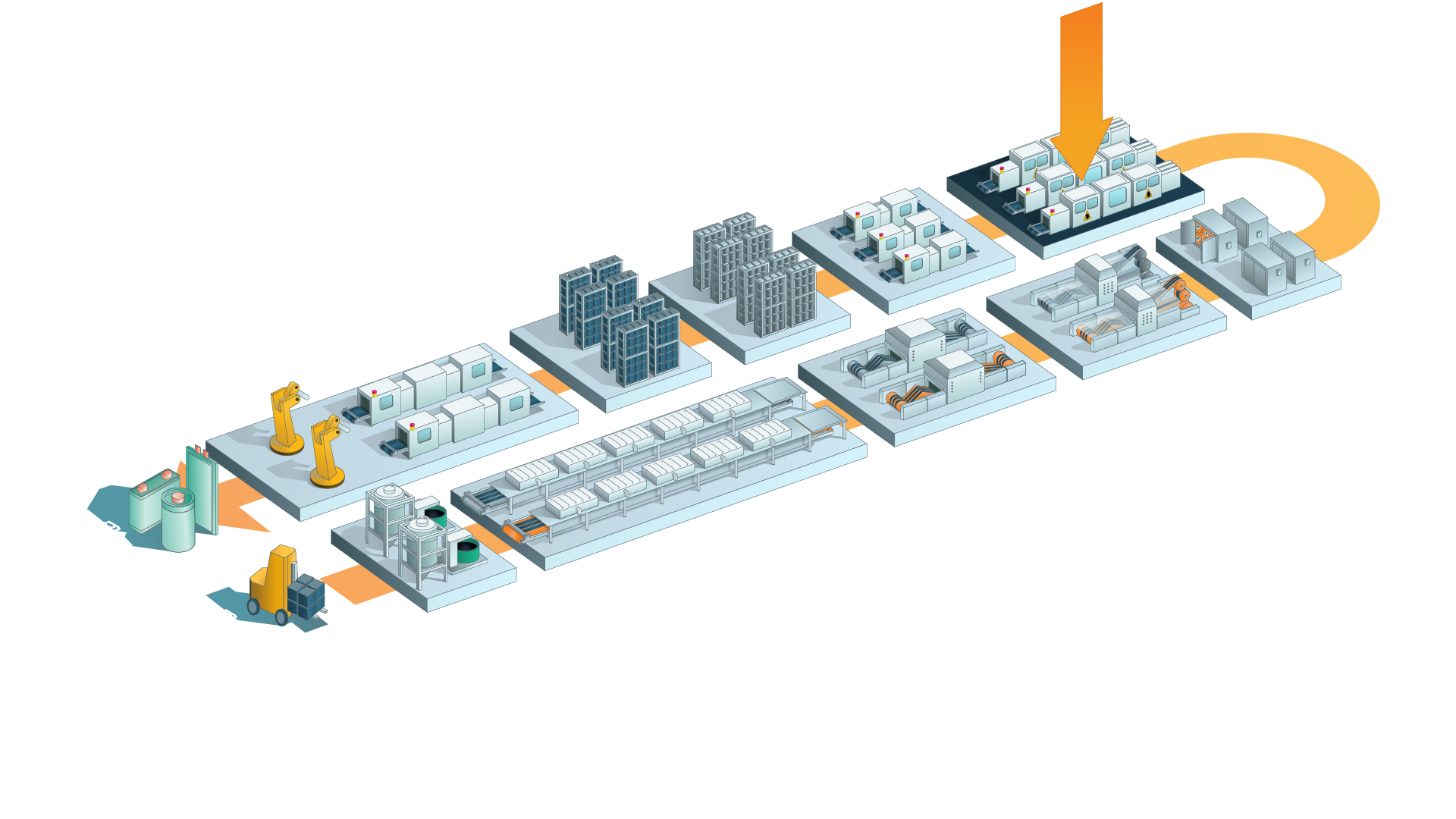
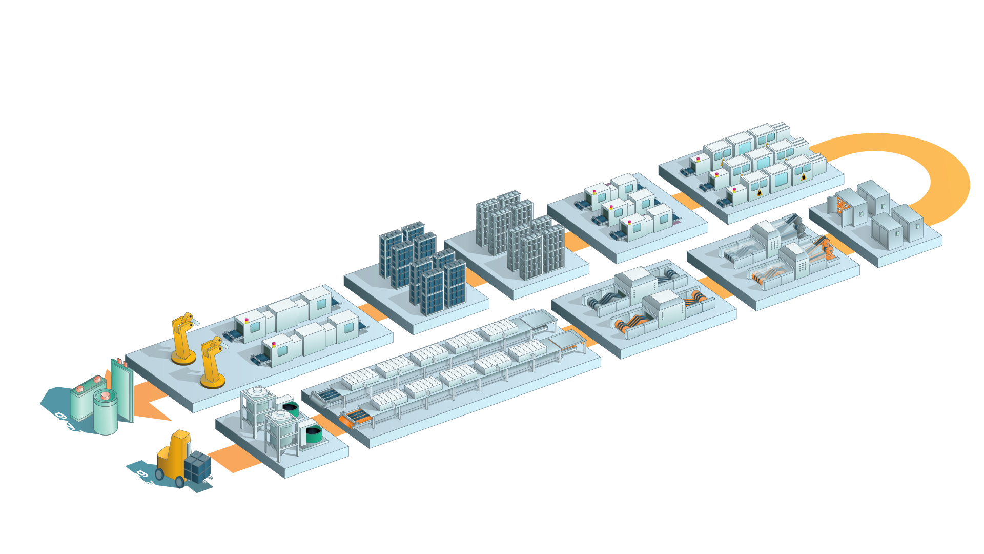
This page presents key emerging technologies in the field of battery cell production. The goal is to provide a structured overview of technological innovations and their potential impact on future manufacturing processes. Each technology is assessed across multiple dimensions to highlight its relevance for battery cell manufacturing. The reference process is the given lithium-ion battery production process on “Battery Production Layout”. The evaluation is referenced to the individual process step. The main evaluation criteria are illustrated using the following symbols:
- Cost: Assesses potential savings in ongoing production costs compared to the current state.
- Energy: Indicates the extent to which energy consumption can be reduced or optimized for the process step while maintaining consistent throughput.
- Quality: Reflects the impact on mainly on product quality and process stability.
- Throughput: Evaluates changes in output volume over a given period and can be increased by parallelization of production lines or machinery.
- Workforce: Estimates whether more or fewer personnel will likely be required compared to today’s operations.
Additionally, each technology is assigned a Technology Readiness Level (TRL) to indicate its development stage – from basic principles (TRL 1) to proven industrial application (TRL 9). Since many of these technologies are still under development, the values presented should be considered preliminary estimates and may be adjusted over time. The assessment is based on the assumption that the process step is scaled to series production.
Dosing and Mixing
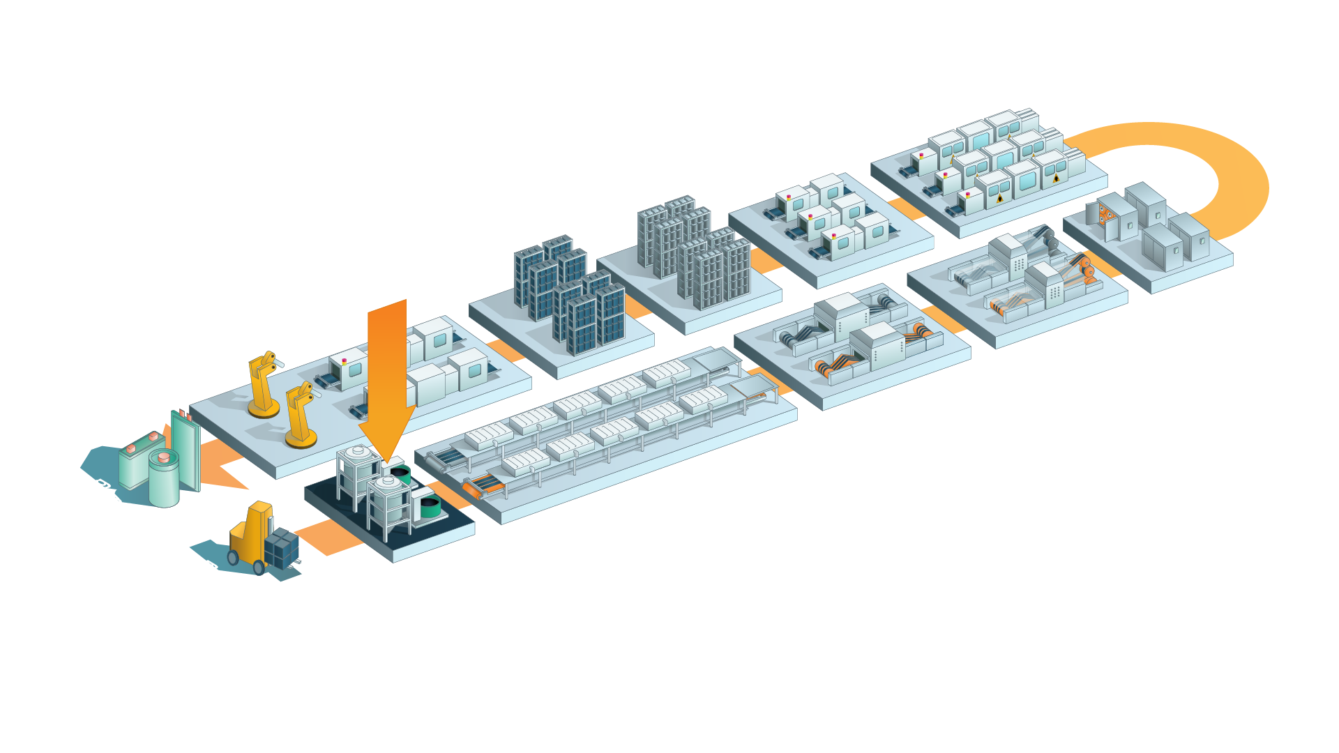
The technologies described below change or impact the dosing and mixing step.
Continuous mixing (Twin-screw extruder)
Impact on Process Step
Cost
-5 %
Energy
-75 %
Quality
+20 %
Throughput
0 %
Workforce
0 %
Footprint
-45 %
TRL
7-8
Process Step

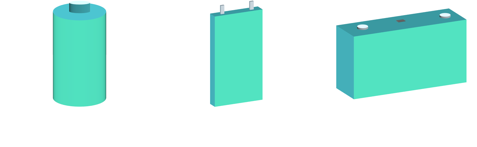
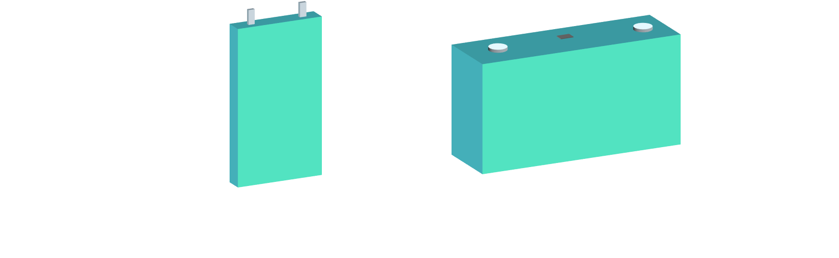
Suitable Formats
Description
A co-rotating, intermeshing twin-screw extruder moves, shears, and blends the electrode ingredients in a continuous flow. Active material, additives, and binder solution are precisely metered into different temperature-controlled sections of the barrel and thoroughly dispersed, producing a uniform, high-solids slurry. After homogenization, the slurry goes straight to the coater. Alternatively, with an integrated die, the slurry is coated inline onto the current collector, eliminating the need for interim storage. [1],[2]
Process Implementation:
Since the equipment runs continuously, batch sampling is no longer possible. Therefore, inline sensors are recommended for real-time monitoring of solids content, dispersion quality, and rheology to enable closed-loop control.
Sustainability:
Compared with conventional batch mixers, continuous twin-screw mixing can lower the specific energy demand of the mixing step by up to 60%. Proportionally, CO₂ emissions from that step drop as well. However, the impact on the total production line is smaller because mixing only accounts for part of the overall energy use. By enabling higher solids content, the extruder boosts throughput, shortens drying time, and brings total energy savings for the combined mixing-and-drying section to about 75% [1].
Key Player: Coperion; Thermo Fisher Scientific; Bühler; LinGod; JWELL Machinery Co., Ltd.; Xiamen Tob New Energy Technology Co., Ltd.; Nanjing Zhitian Mechanical And Electrical Co., Ltd.
Sources
[1] Penningh, N.; Helmers, L.; Wiegmann, E.; Kwade, A. (2023): Application Fields of Extrusion Coating for Battery Manufacturing: A Mini Review.
[2] Haarmann, M.; Haselrieder, W.; Kwade, A.; (2020): Extrusion-Based Processing of Cathodes: Influence of SolidContent on Suspension and Electrode Properties.
Trajectory mixing
Impact on Process Step
Cost
-18 %
Energy
-80 %
Quality
+10 %
Throughput
0 %
Workforce
0 %
Footprint
-78 %
TRL
6-7
Process Step
Suitable Formats
Description
Trajectory mixing eliminates the need for internal agitators. Instead, the cylindrical vessel oscillates along a programmed, two-dimensional Lissajous path. The resulting acceleration fields uniformly disperse the powder, binder, and solvent in micro-batches. Once homogeneous, the slurry is pumped to storage or directly to the coater through fully enclosed piping, enabling straightforward automation of the feed and discharge streams. [1],[2]
Process Implementation:
Pilot trials show that trajectory mixing completes a micro-batch in about one to two minutes, which is roughly 99% faster than the multi-hour planetary cycles that are common today. Because the slurry remains in the vessel for such a short time, it scarcely heats up, so no separate cooling loop is required. With no internal shafts or blades, the mixer has few wear parts, and its smooth, cylindrical pot can be rinsed and inspected in minutes. This sharply reduces maintenance and cleaning downtime. [1],[2]
Sustainability:
The average energy demand is about 9 Wh L⁻¹, which is approximately 98% less than a planetary mixer and roughly half that of an intensive mixer. Proportionally, CO₂ emissions drop as well. [1]
Key Player: HS-Tumbler; PEM RWTH Aachen
Sources
[1] Kamker, A.; Heimes, H.; Wennemar, S.; Bockey, G.; Stellbrink, P.; Hukelmann, B. (2023): TRAJECTORY MIXING INNOVATIVE BATTERY PROCESSING: Rethinking Slurry Production with Ultra-Fast Micro Batches.
[2] HS-Tumbler (2025, 07. July): Trajectory Mixing in Energy Storage Technology: https://www.hs-tumbler.com/Home_en/energy-solutions.
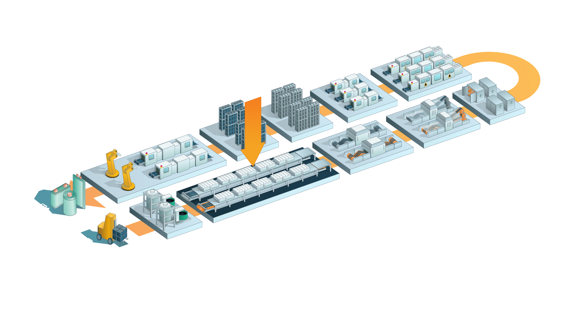
Coating and Drying
Extrusion-based coating
Impact on Process Step
Cost
-6 %
Energy
-23 %
Quality
+20 %
Throughput
0 %
Workforce
0 %
Footprint
-80 %
TRL
5
Process Step


Suitable Formats
Description
In an extrusion-based line, a co-rotating twin-screw extruder first disperses the active material, conductive additive, and binder into a high-solids paste. The paste is then transferred to a single-screw coating extruder. This extruder forces the material through a flat die and deposits a continuous film directly onto the moving current-collector foil. An immediate downstream polishing (nip-roll) or light calendering step evens out the wet layer to the target thickness. [1],[2]
Process Implementation:
Since planetary mixers cannot handle the viscosity of high-solids paste, the twin-screw extruder must either act as the primary mixer or the feedstock must be prepared in a dedicated upstream extruder. Under these high-solids conditions, laboratory trials show that drying-oven residence times are up to 80% shorter than with conventional slot-die coatings, which boosts overall line throughput. [3],[4]
Sustainability:
A higher solids content reduces the demand for solvents and, consequently, the energy required for evaporation. The twin-screw extruder’s lower specific mixing energy further reduces power usage, resulting in a decrease in overall energy consumption and CO₂ emissions compared to the conventional batch-mix/slot-die process. [1],[3],[5]
Key Player: Thermo Fisher Scientific; Nordson; Coperion; Fraunhofer IKTS; JWELL Machinery Co., Ltd.; Xiamen Tob New Energy Technology Co., Ltd.; Nanjing Zhitian Mechanical And Electrical Co., Ltd.
The described process improvements depend on the use of slurry with a solid content of 75%.
Sources
[1] Penningh, N.; Helmers, L.; Wiegmann, E.; Kwade, A. (2023): Application Fields of Extrusion Coating for Battery Manufacturing: A Mini Review.
[2] Seeba, J.; Reuber, S.; Heubner, C.; Müller‑Köhn, A.; Wolter, M.; Michaelis, A.; (2020): Extrusion‑based fabrication of electrodes for high‑energy Li‑ion batteries.
[3] Schünemann, J.-H.; Dreger, H.; Bockholt, H.; Kwade, A.; (2016): Smart Electrode Processing for Battery Cost Reduction.
[4] Gonçalves, R.; Lanceros-Méndez, S.; Costa, C. M.; (2022): Electrode fabrication process and its influence in lithium‑ion battery performance: State of the art and future trends.
[5] Haarmann, M.; Haselrieder, W.; Kwade, A.; (2020): Extrusion-Based Processing of Cathodes: Influence of SolidContent on Suspension and Electrode Properties.
Dry Coating: Electrostatic spraying
Impact on Process Steps
Cost
-81 %
Energy
-85 %
Quality
+30 %
Throughput
-20 %
Workforce
-76 %
Footprint
-95 %
TRL
3-5
Process Step

Suitable Formats
Description
Electrostatic spraying applies a dry, solvent-free powder blend directly to the current collector foil. During this process, a spray gun fluidizes and charges the particles electrically. The grounded foil then attracts the charged powder, forming a uniform layer. A subsequent hot-roll or light-calender pass fuses the binder, providing the electrode with mechanical strength and chemical stability. [1],[2],[5]
Process Implementation:
Since no solvent is used, the dry blend must be mixed thoroughly to ensure the binder is evenly distributed throughout the powder. Once this prerequisite is met, conventional drying and vacuum drying ovens can be eliminated. [3]
Roll-to-roll electrostatic guns enable precise control of coating weight and uniformity via voltage, powder feed, and traverse speed settings. [2]
Sustainability:
Eliminating solvents reduces toxic emissions and the high energy demand of drying ovens. [4] According to AM Batteries’ data, energy consumption and CO₂ emissions are expected to decrease the battery manufacturing process by approximately 40%. [6]
Key Player: Toyota, AM Batteries; DragonFly Energy
Sources
[1] Ludwig, B.; Zheng, Z.; Shou, W.; Wang, Y.; Pan, H.; (2016): Solvent-Free Manufacturing of Electrodes for Lithium-Ion Batteries.
[2] Park, J.; Kim, J.; Kim, J.; Kim, M.; Song, T.; Paik, U.; (2025): Sustainable and cost-effective electrode manufacturing for advanced lithium batteries: the roll-to-roll dry coating process.
[3] Jin, W.; Song, G.; Yoo, J.-K.; Jung, S.-K.; Kim, T.-H.; Kim, J.; (2024): Advancements in Dry Electrode Technologies: Towards Sustainable and Efficient Battery Manufacturing.
[4] Lu, Y.; Zhao, C.-Z.; Yuan, H.; Hu, J.-K.; Huang, J.-Q.; Zhang, Q.; (2022): Dry electrode technology, the rising star in solid-state battery industrialization.
[5] Al-Shroofy, M.; Zhang, Q.; Xu, J.; Chen, T.; Kaur, A. P.; Cheng, Y.-T.; (2017): Solvent-free dry powder coating process for low-cost manufacturing of LiNi₁/₃Mn₁/₃Co₁/₃O₂ cathodes in lithium-ion batteries
[6] E. B. Bonomo; (2024): Making Batteries More Efficiently: AM Batteries Powder to Electrode Method. https://time.com/7094943/am-batteries-powder-to-electrode-method/
Dry Coating: Brush application
Impact on Process Steps
Cost
-81 %
Energy
-80 %
Quality
+30 %
Throughput
+/-10 %
Workforce
-76 %
Footprint
-95 %
TRL
4
Process Step
Suitable Formats
Description
In the brush application variant of dry coating, a premixed powder containing active material, conductive carbon, and a binder is dosed onto a rotating needle roller. As the roller turns, a brush removes the excess powder and evenly distributes it onto the moving current collector foil. A subsequent pass through a hot roll (or light calender) compacts the layer, melts or fibrillates the binder, and provides the electrode with mechanical strength and chemical stability. [1],[2]
Process Implementation:
Because there is no solvent present, the dry-mixing step upstream must ensure the binder particles are uniformly distributed to form a continuous network during hot rolling. Eliminating the solvent also removes the drying and vacuum drying sections from the process. [3]
Sustainability:
Eliminating solvents reduces the use of hazardous materials and avoids the high energy demand of convection dryers. Fraunhofer ISIT’s benchmark shows up to an 80% reduction in energy consumption and CO₂ emissions in the coating area. [4]
Key Player: Fraunhofer ISIT; Technische Universität Braunschweig
Sources
[1] Degen, F.; Krätzig, O.; (2024): Future in Battery Production: An Extensive Benchmarking of Novel Production Technologies as Guidance for Decision Making in Engineering.
[2] Fraunhofer ISIT (2025, 07. July): Dry Coating: https://www.isit.fraunhofer.de/en/FAB-SH/dry-coating.html.
[3] Jin, W.; Song, G.; Yoo, J.-K.; Jung, S.-K.; Kim, T.-H.; Kim, J.; (2024): Ad-vancements in Dry Electrode Technologies: Towards Sustainable and Efficient Battery Manufacturing.
[4] Lu, Y.; Zhao, C.-Z.; Yuan, H.; Hu, J.-K.; Huang, J.-Q.; Zhang, Q.; (2022): Dry electrode technology, the rising star in solid-state battery industrialization.
Dry Coating: Electrostatic fluidized bed deposition
Impact on Process Steps
Cost
-81 %
Energy
-85 %
Quality
+30 %
Throughput
n.a
Workforce
-76 %
Footprint
-95 %
TRL
6
Process Step
Suitable Formats
Description
In electrostatic fluidized-bed (EFB) coating, a solvent-free powder blend is aerated through a porous distributor plate to form a homogeneous fluidized bed. As the particles collide inside the bed, they become tribo-charged. When a grounded copper or aluminum foil passes over the bed, the electrostatic field attracts the charged powder to the surface, forming a uniform layer. A downstream hot roll (light calender) compacts the layer, activates the binder by melting or fibrillating it, and imparts the required mechanical strength and chemical stability. [1], [2]
Process Implementation:
Since there is no solvent available to dissolve the binder, the dry-mixing step must distribute the binder particles evenly so they can coalesce during hot rolling. Eliminating the solvent also removes the drying oven and vacuum drying section. According to pilot studies, high web speeds are currently limited by particle-size segregation in the fluidized cloud. Achieving industrial throughputs will require either narrow PSDs or active cloud agitation. [3]
Sustainability:
The absence of solvent reduces hazardous emissions and eliminates the significant energy consumption of convection dryers. This results in a substantial decrease in energy use and CO₂ emissions compared to wet-coating lines. [4]
Key Player: Fraunhofer IPA; Technische Universität Braunschweig
Sources
[1] Degen, F.; Krätzig, O.; (2024): Future in Battery Production: An Extensive Benchmarking of Novel Production Technologies as Guidance for Decision Making in Engineering.
[2] Ludwig, B.; Zheng, Z.; Shou, W.; Wang, Y.; Pan, H.; (2016): Solvent-Free
[3] Khan, F. M. N. U.; Rasul, M. G.; Sayem, A. S. M.; Mandal, N. K.; (2022): Maximizing energy density of lithium‑ion batteries for electric vehicles: A critical review.
[4] Lu, Y.; Zhao, C.-Z.; Yuan, H.; Hu, J.-K.; Huang, J.-Q.; Zhang, Q.; (2022): Dry electrode technology, the rising star in solid-state battery industrialization.
Dry Coating: Free-standing electrode fabrication
Impact on Process Steps
Cost
-81 %
Energy
-85 %
Quality
+30 %
Throughput
n.a
Workforce
-76 %
Footprint
-95 %
TRL
6
Process Step
Suitable Formats
Description
A dry blend of active material, conductive carbon, and polytetrafluoroethylene (PTFE) binder is shear-processed so that PTFE fibrillates and forms a cohesive, free-standing electrode film. This tape is then hot-laminated onto the aluminum or copper current collector before standard downstream steps. The key distinction versus other dry processes is that the film is formed off-foil and only afterward bonded to the collector. [1],[2]
Process Implementation:
Reliable operation requires intensive dry mixing to achieve sufficient PTFE fibrillation and a fine binder distribution throughout the composite. The lamination window (temperature, pressure, and dwell time) must be tuned to the collector surface to ensure adhesion without inducing cracks or embrittlement. Using the dry route eliminates the need for convection and vacuum drying, as well as solvent recovery, thereby shortening the process chain. [3]
Sustainability:
Removing solvent reduces energy consumption and associated CO₂ emissions by eliminating the need for drying ovens and solvent handling. Because PTFE is a fluoropolymer, local regulations may require additional environmental, health, and safety (EHS) measures, such as safe handling, emissions control, and defined end-of-life disposal. [4],[5]
Key Player: Maxwell Technologies (Tesla); Panasonic; rexroth (Bosch); SVOLT; DAIKIN Global; Saueressig (matthews engineering); LG Energy Solution Ltd
Sources
[1] Degen, F.; Krätzig, O.; (2024): Future in Battery Production: An Extensive Benchmarking of Novel Production Technologies as Guidance for Decision Making in Engineering.
[2] Park, J.; Kim, J.; Kim, J.; Kim, M.; Song, T.; Paik, U.; (2025): Sustainable and cost-effective electrode manufacturing for advanced lithium batteries: the roll-to-roll dry coating process.
[3] Jin, W.; Song, G.; Yoo, J.-K.; Jung, S.-K.; Kim, T.-H.; Kim, J.; (2024): Advancements in Dry Electrode Technologies: Towards Sustainable and Efficient Battery Manufacturing. Advancements in Dry Electrode Technologies: Towards Sustainable and Efficient Battery Manufacturing
[4] Lu, Y.; Zhao, C.-Z.; Yuan, H.; Hu, J.-K.; Huang, J.-Q.; Zhang, Q.; (2022): Dry electrode technology, the rising star in solid-state battery industrialization.
[5] Donley, N.; Cox, C.; Bennett,K.; Temkin, A.; Andrews, T.; Naidenko, O. (2024): Forever Pesticides: A Growing Source of PFAS Contamination in the Environment
Dry Coating: Direct calendering
Impact on Process Steps
Cost
-85 %
Energy
-88 %
Quality
+30 %
Throughput
+25 %
Workforce
-81 %
Footprint
-96 %
TRL
6-7
Process Step
Suitable Formats
Description
In direct calendering, a blend of solvent-free powders (active material, conductive carbon, and PTFE binder) is metered into the nip between two heated, counter-rotating rolls. Within this calender gap, the PTFE is fibrillated by shear and compressive stresses, forming a coherent dry film on the surface of the faster roll. Supported by the roll train, the film is transferred at a subsequent lamination nip against the current-collector foil wrapped over an opposing roll, bonding without ever leaving the roller system. [1],[2]
Process Implementation:
The in-line film formation/lamination sequence allows for a compact layout and can be configured for double-sided coating in a single pass. Whether a separate post-calender is needed depends on the recipe. Compaction can be integrated into the lamination nip, but additional calendering may still be required to meet porosity and adhesion targets. [1]
Sustainability:
Removing solvent eliminates drying and solvent-recovery, reducing energy use and associated CO₂ emissions for this process section. Because PTFE is a fluoropolymer, local regulations may require additional environmental, health, and safety (EHS) measures, such as safe handling, emissions control, and defined end-of-life disposal.[3],[4]
Key Player: Fraunhofer IWS; Saueressig (Matthews Engineering); Koenig and Bauer
Sources
[1] Degen, F.; Krätzig, O.; (2024): Future in Battery Production: An Extensive Benchmarking of Novel Production Technologies as Guidance for Decision Making in Engineering.
[2] Fraunhofer IWS (2025, 07. July): DRYtraec® Technology: https://www.drytraec.de/en/technology.html
[3] Lu, Y.; Zhao, C.-Z.; Yuan, H.; Hu, J.-K.; Huang, J.-Q.; Zhang, Q.; (2022): Dry electrode technology, the rising star in solid-state battery industrialization.
[4] Donley, N.; Cox, C.; Bennett,K.; Temkin, A.; Andrews, T.; Naidenko, O. (2024): Forever Pesticides: A Growing Source of PFAS Contamination in the Environment.
Multilayer Coating
Impact on Production
Cost
n.a.
Energy
n.a.
Quality
+30 %
Throughput
+650 %
Workforce
-87 %
Footprint
-75 %
TRL
3-4
Process Step
Suitable Formats
Description
Conventional slot-die lines deposit one slurry layer per pass. Multilayer coating via simultaneous multilayer slot-die or curtain/slide applies to at least two layers in one or subsequent coatings. This process enables graded electrodes while maintaining roll-to-roll compatibility. [1],[2]
Process Implementation:
One-pass, two-layer deposition reduces coating runs and drying time, boosting throughput. Stable operation requires matched viscosity and surface tension to maintain layer separation, plus tuned dryer profiles to prevent interlayer mixing at production speed. The downstream stations and quality control (QC) routines need to be adjusted. [2]
Sustainability:
The assessment is not yet available.
Key Player: 8INKS (Thermo Fisher Scientific, ETH Zürich); Infinitypv; ISOF; TSE Troller
Sources
[1] TSE Coating (2007): Curtain coating – an overview.
[2] 8ink (2025, 07. July): The Multilayer Battery Company: https://8inks.com/
Drying: Vertical-Cavity Surface-Emitting Laser (VCSEL)
Impact on Process Step
Cost
-68 %
Energy
-68 %
Quality
0 %
Throughput
+90 %
Workforce
-47 %
Footprint
-75 %
TRL
5
Process Step
Suitable Formats
Description
Vertical-Cavity Surface-Emitting Laser (VCSEL) arrays that are mounted close to the web emit 980-nm infrared light that is strongly absorbed by the electrode coating. This heats the coating rapidly and evaporates the solvent. VCSELs can operate independently or in hybrid mode with conventional dryers. In tests, hybrid drying reduced drying time by ~45% with a quality comparable to stand-alone convection drying.
A stand-alone VCSEL reduced drying time by over 80%. Despite slightly lower adhesion and marginally higher residual moisture, the electrochemistry and SEM results remained comparable. [1],[2]
Process Implementation:
Compact, retrofittable vertical-cavity surface-emitting laser (VCSEL) modules mount close to the web and offer multi-zone power control with a response time of ~10 ms for closed-loop drying profiles. The modules can run independently or as hybrid stages with convection. Power density and dwell time are adjusted to prevent binder migration and achieve residual moisture targets. [1]
Sustainability:
Direct heating and instant ramping reduce warm-up and standby losses, which can shrink the dryer’s footprint. Replacing or downsizing convection reduces energy use and CO₂ emissions for the drying section. Savings depend on the recipe and production line. [1]
Key Player: Trumpf; PEM RWTH Aachen; Lemon Photonics
Sources
[1] TRUMPF Photonic Components; PEM RWTH Aachen (2024): VCSEL laser drying in battery production: A solution for cost-effective electrode manufacturing.
[2] Wang, H.; Chen, Y.; Song, Y.; Xiong, D.; (2025): Rapid electrode drying for high‑quality lithium‑ion batteries: A three‑stage laser irradiation method.
Drying: Diode laser
Impact on Process Step
Cost
-59 %
Energy
-72 %
Quality
0 %
Throughput
+80 %
Workforce
-44 %
Footprint
-94 %
TRL
4
Process Step
Suitable Formats
Description
High-power diode lasers mounted above the roll-to-roll web deliver near-infrared (NIR) energy, which is absorbed by the electrode coating. This rapidly heats the layer and evaporates the solvent. These systems can operate independently or in hybrid mode with convection drying. Pilot results indicate that hybrid mode achieves higher drying speeds with comparable adhesion and residual moisture. [1],[2]
Process Implementation:
Compact, retrofit-ready diode laser modules use beam-shaping optics to adjust the spot or line geometry and working distance. The power density and dwell time are adjusted according to the recipe and coating thickness. In hybrid setups, the laser stages are positioned immediately before or after the hot-air (convection) oven. Zone power is closed-looped with in-line sensors to ensure that residual moisture and adhesion targets are met. [1],[2]
Sustainability:
Near-infrared (NIR) technology heats the coating directly, and lasers ramp up instantly. This cuts warm-up and standby losses, enabling shorter dryer sections. It is possible to reduce the number of convective dryers for this process. This requires less energy and associated CO₂ emissions during the drying stage.[3]
Key Player: Laserline; IPG Photonics; PEM RWTH Aachen; Fraunhofer ILT & FFB
Sources
[1] Fraunhofer ILT: Press Release (2025): Laser Drying Technology Takes Leap Forward: IDEEL Project Demonstrates Scalability for Efficient Battery Cell Production.
[2] Laserline GmbH; PEM RWTH Aachen (2023): Diode Laser Drying of Electrodes for Lithium‑Ion Batteries: Paving the Way for Energy‑Efficient and Economical Battery Production.
[3] Laserline GmbH (2025, 07. July): Laser Drying https://www.laserline.com/en-int/laser-drying/#c4678
Drying: Near-Infrared (NIR)
Impact on Process Step
Cost
-59 %
Energy
-90 %
Quality
0 %
Throughput
+50 %
Workforce
-33 %
Footprint
-93 %
TRL
8
Process Step
Suitable Formats
Description
Near-infrared (NIR) emitters, which operate at wavelengths of ~0.76–2 µm, are mounted above the roll-to-roll line. They deliver radiant energy that is primarily absorbed by the electrode coating. This rapidly heats the layer and evaporates the solvent. NIR can operate independently or as a hybrid stage with hot-air drying to increase drying speed while meeting adhesion and residual moisture targets. [1],[2]
Process Implementation:
Near-infrared (NIR) modules can be retrofitted into the drying section as pre- or post-dryers around the hot-air (convection) oven. They are mounted close to the coated foil, and the irradiance and emitter-to-foil distance are adjusted for each coating using zoned, closed-loop power control. The rest of the line remains unchanged, and the drying section can be shortened, or the convection load can be reduced.[3]
Sustainability:
Direct, instant-ramp heating reduces energy consumption and CO₂ emissions during the drying step. Actual savings depend on formulation and integration. [1]
Key Player: NGK Insulators; NobleLight; UV-Technik Hoenle company; Adphos; MICRO; PEM RWTH Aachen
The described process Improvements are relative to conventional hot-air (convection) drying.
Sources
[1] Schütte, M.; Degen, F.; Walter, H.; (2024): Reducing Energy Consumption and Greenhouse Gas Emissions of Industrial Drying Processes in Lithium‑Ion Battery Cell Production: A Qualitative Technology Benchmark.
[2] MICOR GmbH (2025, 07.July): The Right Wavelength: Heating and Drying with MICOR *NIR Technology: https://www.micor.de/en/nir-technology
[3] Horstig, M.; Schoo, A.; Loeffhoeffel, T.; Mayer, J.K.; Kwade, A. (2022): A Perspective on Innovative Drying Methods for Energy‑Efficient Solvent‑Based Production of Lithium‑Ion Battery Electrodes.
Vacuum Drying
Roll-to-Roll Vacuum Drying
Impact on Process Step
Cost
-39 %
Energy
-50 %
Quality
0 %
Throughput
0 %
Workforce
-50 %
Footprint
-90 %
TRL
7
Process Step
Suitable Formats
Description
In the traditional post-drying process, slit daughter coils are treated in batch vacuum ovens for many hours, which can cause roll-center/edge non-uniformity. In contrast, roll-to-roll (R2R) vacuum drying unwinds the coil and dries the electrode as a continuous web under vacuum with zoned heating. Then, it rewinds the coil, turning a batch operation into a continuous one and improving drying uniformity. [1]
Process Implementation:
R2R vacuum modules, placed after slitting, remove roll parking and chamber cycles. Vendors report drastic reductions in cycle time versus batch vacuum (e.g., 12 hours to 0.6 hours), thanks to integrated multi-zone heating and tension control. [1]
Sustainability:
Compared with batch vacuum drying, roll-to-roll vacuum drying can lower power demand and footprint. Some designs also eliminate the need for a nitrogen purge, which reduces operating costs and CO₂ emissions. [1]
Key Player: EandR Group; Daiichi Jitsugyo Co., Ltd.; Leybold; NGK Insulators; SIDRABE
Sources
[1] DAIICHI JITSUGYO CO., LTD. (2025, 07. July): Vacuum Roll to Roll Drying System: https://djk-energysolutions.com/index.cgi?mode=product_list&prc_code=flow14
[2] NGK Insulators (2025, 07. July): Continuous Drying Furnaces for Lithium-Ion Battery Electrode Substrate Dehydration (Absolute Drying) Processes: https://www.ngk-insulators.com/en/product/recommend/hd-roll-lib.html
Assembly
The technologies described below change or impact the assembly step.
Rotative High-Speed Single Sheet Stacking
Impact on Process Step
Cost
-90 %
Energy
-90 %
Quality
0 %
Throughput
+900 %
Workforce
-90 %
Footprint
-90 %
TRL
3-4
Process Step

Suitable Formats
Description
Rotative high-speed single-sheet stacking is a high-throughput method for assembling lithium-ion electrode stacks.
A multi-pocket stacking wheel receives anode and cathode sheets via parallel conveyors. The wheel then transports the sheets continuously and releases them into a stacking compartment using stationary stripper arms. In the compartment, the stack is aligned and compressed. In some implementations, pre-laminated electrodes with a separator reduce the number of parts and handling steps. The rotary single-sheet method is a high-throughput alternative to the Z-fold method. [1]
Process Implementation:
The rotary unit enables continuous flow and parallel feeding, achieving a higher throughput than pick-and-place. Deposition accuracy depends on the design of the wheel and pocket, as well as the timing. [2] Pre-laminating the separator to one electrode can simplify handling further. [3]
Sustainability:
No significant improvements.
Key Player: Volkswagen Group; TU Braunschweig; ABB Ltd
Sources
[1] Volkswagen AG (2019): DE102019205428A1
[2] von Boeselager, C.; Kapelar, M. O.; Dröder, K.; (2022): Multi-Body Simulation of a Novel Electrode Stacking Process for Lithium-Ion Battery Production.
[3] von Boeselager, C.; Vogt, S.; Wacker, C.; Dröder, K.; (2024): Enhanced Deposition Accuracy for Battery Electrodes in a Novel High-Speed Stacking Process.
Across Processes
The technologies described below change or impact the whole production line.
Pre-Lithiation
Impact on Production
Cost
-8 %
Energy
+34 %
Quality
+30 %
Throughput
+4,5 %
Workforce
-12,5 %
Footprint
-11,5 %
TRL
7-8
Process Step

Suitable Formats
Description
Pre-lithiation adds lithium to offset initial losses due to the formation of the solid-electrolyte interphase (SEI) and other parasitic reactions. This process increases the first-cycle coulombic efficiency (CE) and recovers capacity/energy, which is particularly helpful for high-silicon anodes. There are two approaches: anode (direct-contact, electrochemical, and additive-assisted) and cathode (over-lithiation and sacrificial additives). These approaches can be integrated at the electrode or cell-assembly stage. [1]
Process Implementation:
Pre-lithiation involves adding a short station to the production line that applies a precise amount of lithium to the electrode. Since lithium reacts with air and moisture, this step takes place in a dry, protected environment with defined safety measures. The effects on adjacent process steps require further evaluation and integration studies. [1],[2]
Sustainability:
The added station increases electricity use, including dry-room load, as well as lithium and additive consumption. This raises the CO₂ and material footprints for that step. [3]
Key Player: ACE Tech; RENA; Nanoscale Components; MEET Universität Münster; ISEA RWTH Aachen
Sources
[1] Sun, C.; Zhang, X.; Li, C.; Wang, K.; Sun, X.; Ma, Y.; (2020): Recent advances in prelithiation materials and approaches for lithium-ion batteries and capacitors.
[2] Diller, F.; Günthner, M.; Stumper, B.; Daub, R.; (2024): Towards the Integration of Direct Contact Prelithiation into the Manufacturing Process for Large-Format Lithium-Ion Batteries.
[3] Orangi, S.; Manjong, N. B.; Perez Clos, D.; Burheim, O. S.; Strømman, A. H.; (2024): A bottom-up framework to investigate environmental and techno-economic aspects of lithium-ion batteries: A case study of conventional vs. pre-lithiated lithium-ion battery cells.
Mini-Environments
Impact on Production
Cost
-12 %
Energy
-29 %
Quality
+10 %
Throughput
0 %
Workforce
-10 %
Footprint
0 %
TRL
7-8
Process Step


Suitable Formats
Description
Mini-environments enclose individual tools or a whole machines and provide ultra-dry and clean conditions at the machine, rather than conditioning an entire room. Inside the enclosure, the temperature, cleanliness, and dew point are tightly controlled (typically ≤ -40 °C and, for sensitive processes, down to approximately -60 °C), while the surrounding area can operate under less stringent specifications.[1]
Process Implementation:
The systems use sealed housings with a dedicated air supply and return, filtration, and dew-point control. They also have airlocks for material transfer and built-in monitoring of the dew point, particles, and airflow. While they improve the handling of moisture-sensitive steps, they also increase integration and maintenance complexity due to added interfaces and reduced accessibility. [2],[3]
Sustainability:
By shrinking the volume of air that must be dried and filtered, mini-environments can reduce the energy consumption for air treatment and associated CO₂ compared with full-room dry/clean concepts. The actual benefit depends on which process steps are enclosed, leakage rates, and the production layout. [4]
Key Player: Exentec (Exyte Gruppe); weisstechnik; Fraunhofer FFB / ISE; Connect 2 Cleanrooms; ULT AG; ProCleanroom
These improvements are relative to the given reference process, “Battery Cell Production Layout” and depend on achieving the targeted throughput gains.
Sources
[1] Fraunhofer ISE (2024): Investigating requirements on mini-environments for ultra-low dewpoint applications.
[2] Plocher, L.; Heller, M.; Ingendoh, B.; Turhan, H.; Burgard, M.; Wennemar, S.; Kampker, A.; Kissling, M.; (2023): Mini-Environments in Lithium‑Ion Battery Cell Production: A Survey on Current State, Challenges and Trends.
[3] exentec (2025, 07. July): DRYOON: https://www.exentec.net/Products/Mini-Environments/Dryoon
[4] Heller, M.; Wessel, S.; Wilk, T.; (2023): Techno‑Economic Development Methodology for Mini‑Environments in Battery Cell Production.